This device driver enables you to create your own set of items from the Fanuc FOCAS library, without the need for programming! In addition to monitoring and output a broad spectrum of process data it allows you to dynamically define and change items on a per machine basis with an INI file while CNCnetPDM is running.
This device driver requires the most recent version of CNCnetPDM and also works with a free license. However, in this mode you only get output for the first item configured in your INI file. With a valid license you are able to output the result of up to 30 functions per reading cycle, see licensing for details.
FUNCTIONS
The following functions are included and can be used and modified in the standard version of this driver. If you need additional functions we can add them at a fixed price. Please contact us to get a quote!
Read alarm status, program number in execution, program number of main program, actual sequence number, actual feed rate, actual spindle speed (Ethernet: cnc_rddynamic2 HSSB: cnc_rddynamic)
Read absolute, machine and relative position of axis and amount of distance to go (Ethernet: cnc_rddynamic2 HSSB: cnc_rddynamic)
Read OEE machine state and execution mode, text and/or numeric (cnc_oeestate)
SETUP
Make sure that you have a connection from your PC to the controller and get data, use the fanucdata utility to do so. In case you use HSSB instead of Ethernet please read the additional instructions.
Download the Universal Fanuc driver, if you do not have any Fanuc driver installed extract all content of fanucconf_dll.zip into the folder where you have CNCnetPDM installed. Otherwise it’s sufficient to just extract fanucconf.dll to this folder.
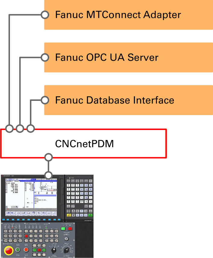
Edit CNCnetPDM.ini and add a new device as described in the quick start guide point 6. If you already have an entry in section [RS232] for a machine with a Fanuc controller you can simply copy and paste this line and change its content.
FIG 2: Add a Fanuc device
For Fanuc controllers the following 4 parameters are important:
The parameter (1) is the port you are using for communication with your controller, 8193 would be Fanuc FOCAS standard.
The next parameter (2), here 0 tells the driver what connection you are using, change it to 1 if you use ‘real’ HSSB or 2 if you use the HSSB functions of NCGUIDE. Zero and every higher number than 2 is Ethernet. In case of HSSB use 127.0.0.1 as IP Address and localhost as DNS Hostname.
Parameter (3) tells the driver how you’d like to acquire part counter values. If you enter 6711 the driver reads parameter 6711 that’s standard on most controllers. Any other number means: Read the number as address from the (PLC) PMC (Area 9).
Change parameter above (4) to fanucconf.dll.
Please also set the following entries in section [GENERAL] of CNCnetPDM.ini to 1 to get all possible items: CollectStates = 1 CollectCounters = 1 CollectFeeder = 1 CollectQuality = 1 CollectOrders = 1
USAGE
Start CNCnetPDM, foreground program is sufficient (Start thread)
CNCnetPDM automatically copies the original fanucconf.dll and appends the machine number as configured in the INI file, e.g. fanucconf_1000.dll for machine 1000.
In addition an INI file with the same name is created by the device driver, e.g. fanucconf_1000.ini for machine number 1000.
Double click CNCnetControl, if your device number is 1000 and the device name is FANUC #1 the output should be similar to the one below:
FIG 3: CNCnetControl (Fanuc)
The machine (1) shows up as connected (2) which is good. On the right side (3) you see the acquired data:
E = Machine state 4 would be interrupted mode, changes to 2 if the machine is in automatic mode and runs a program. 3 would be manual, 5 error.
Z = Part counter value. If you’re counting in cumulative mode you see the part counter value as shown at the operator panel.
The lines starting with O, A or F contain the items you added via the INI file. If you didn’t change the automatically created INI file you get something like the following:
1000 12/03/2023 12:57:18 PM O STATN|4|STATT|Interrupted|MODEN|1|MODET|Memory|MOTIO|0|PRGCU|4|PRGMN|4|SEQCU|11|FEEDR|0|SPSPD|1001|TOOL1|1|CUTFD|5000.000|ALMNR|0|ALMTX|No alarm|TOOL2|1.00000000|PMC01|255| 10000000004
Every item has a description followed by its value. All descriptions and values are delimited by pipe ‘|’ symbols. This allows the most recent version of CNCnetPDM to create a database record for every item.
With an unmodified INI file these items are:
ID
NAME
DESCRIPTION
2
STATN
OEE Machine state number
3
STATT
OEE Machine state text
4
MODEN
Controller mode number
5
MODET
Controller mode text
6
MOTIO
Motion of axis
7
PRGCU
Current NC program
8
PRGMN
Main NC program
9
SEQCU
Current sequence
10
FEEDR
Actual Feed rate
11
SPSPD
Actual Spindle speed
12
AX
Axis position + axis number (multiple values)
11
ALMST
Alarm status number
13
TOOL1
Tool id (modal)
14
CUTFD
Cutting feed rate (parameter)
15
ALMNR
Alarm number
16
ALMTX
Alarm text
17
TOOL2
Tool ID (system macro)
18
PMC01
PMC value (area 0 address 118)
FIG 4: IDs, names and description of default items
The line starting with A contains the current axis position values for up to 7 axes. With an unmodified INI file and a machine with 2 axes you get something similar to the following:
The axis number is appended to the name. The values for each axis are:
First value: Absolute position
Second value: Relative position
Third value: Machine position
Fourth value: Distance to go
INI FILE DESCRIPTION
The device driver enables you to dynamically select items from the Fanuc FOCAS library, group, change, enable or disable them. The INI file automatically created by the device driver for every machine contains a section with the ID number of each item (see table above) e.g. [18] for PMC data:
You can switch acquisition of specific items on or off by altering the value of Active (0 = off, 1 = on). You can also adjust the name of the item by changing the value of Name, up to five characters are possible. For example if you do not need to acquire tool ID via the modal and the parameter function you can switch one of them off. If you do not need axis positions you can also switch it off by setting Active to 0 in section [12] of the INI file.
It is also possible to force output of items to section 1,2 or 3. Items in section 1 go to group prefixed with ‘O’, 2 = ‘A’ and 3 = ‘F’. Make sure you have entries CollectOrders, CollectFeeder and CollectQuality enabled (=1) in CNCnetPDM.ini.
To add or adjust items while CNCnetPDM is running open the INI file with a text editor such as notepad, make the desired changes and save the file. To apply the changes immediately you can click on the machine (1) in CNCnetControl on the left side followed by clicking buttons [Close] (2) and [Open] (3) above the section ‘Devices’.
FIG 5: Reload device INI file
MODIFY ITEMS
As stated the driver allows you to directly add various functions from the Fanuc FOCAS library. Although many of these functions are pretty complex we tried to make it as simple as possible.
To add a function from the library the following items in each INI file section are important:
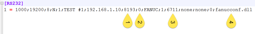
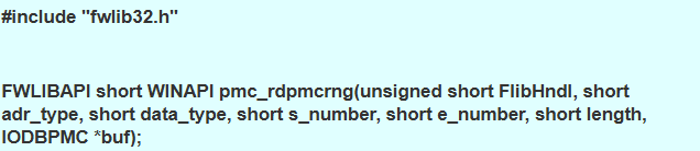
Command is the name of the function (all lowercase). You can find it in the field with cyan background in the documentation right of WINAPI. For pmc_rdpmcrng this would be:
FIG 6: Command and parameters
Input parameters 1-4 are the arguments after ‘unsigned short FlibHndl’ in the specified order. In this example
short adr_type = Input parameter 1, here 0 = G (Signal to PMC->CNC)
short s_number and short e_number = Input parameter 2 (as the driver queries one address per section, you can have multiple sections that call pmc_rdpmcrng!)
short data_type and short length are automatically calculated by the driver depending on the Output item you set in the INI file, here Output item = idata.
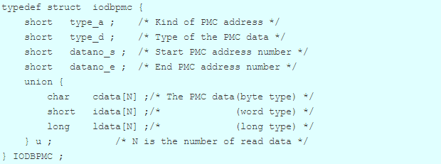
Many of the Fanuc FOCAS functions are able to output different items or data formats. For pmc_rdpmcrng you can find them in the field with cyan background that describes the structure, here iodbpmc.
FIG 7: iodbpmc data structure
The PMC is able to store and output different data formats at each address. If you enter cdata (lowercase without brackets!) for Output item you get byte data from the selected address, for idata you get integer for ldata long and for bdata bits from 0-8 e.g. 01000001.
PARAMETERS
Here you can find all parameters for Fanuc FOCAS functions currently implemented in the standard version of the driver:
cnc_statinfo
Reads various status data. Only ‘Output item’ is required:
tmmode: Selected T/M mode aut: Automatic/manual mode selection run: Status of automatic operation motion: Status of axis movement, dwell mstb: Status of M,S,T,B function emergency: Emergency status alarm: Alarm status edit: Status of program editing
Reads dynamic data, Input parameter 1 and Output item can be adjusted.
‘Input parameter 1’ = axis (-1 for all, 0 for none, 1-n for controlled axes) ‘Output item’ = item e.g. alarm or prgnum that should be output, see typedef struct odbdy2 for both functions. For axis positions you can either input faxis for all or oaxis for a specified axis:
alarm: Alarm status prgnum: Current program number prgmnum: Main program number seqnum: Current sequence number actf: Actual feed rate acts: Actual spindle speed faxis: Axis positions all axes oaxis: Axis positions one axis
Reads and outputs the comment for the current nc-program e.g. outputs 'Part 133 Version A' for O455 (Part 133 Version A). Outputs 'none' if there is no comment. No input parameters are required.
Reads parameter value. To check if specific parameters are available on your controller use our tool to read parameters.
‘Input parameter 1’ = parameter number ‘Input parameter 2’ = axis (-1 for all, 0 for none, 1-n for controlled axes) ‘Output item’ = cdata (byte) idata (integer) ldata (long) rdata (real data with decimal point) or bdata (bits from 0-8 e.g. 01000001).
Reads diagnostic data. To check if specific diagnostic parameters are available on your controller use our tool to read diagnosis parameters.
‘Input parameter 1’ = diagnosis parameter number ‘Input parameter 2’ = axis (-1 for all, 0 for none, 1-n for controlled axes) ‘Output item’ = cdata (byte) idata (integer) ldata (long) rdata (real data with decimal point) or bdata (bits from 0-8 e.g. 01000001).
‘Input parameter 1’ = type, see cnc_modal for details. Please select only types with note ‘one by one’! ‘Input parameter 2’ = block, e.g. 0 = active block, 1 = next block, 2 = block after next block ‘Output item’ = Either aux, raux1, raux2
cnc_alarm
Reads alarm data. Only ‘Output item’ is required: 'number' outputs alarm number 'text' outputs alarm text for your specific controller type.
Improved version of cnc_alarm function. Outputs up to 20 different alarms per controller. Only ‘Output item’ is required: 'number' outputs alarm number 'text' outputs alarm text for your specific controller type.
Both functions read and output detailed alarm messages in case there is an alarm. cnc_rdalminfo is supported by most controllers. Only ‘Output item’ is required: 'message' outputs the current alarm message, 'axis' outputs the axis number for the current alarm.
‘Input parameter 1’ = Axis number, -1 outputs data for all axes, 1 - n outputs data for a specific axis. If an invalid axis number ist entered the function outputs data for axis 1.
Reads PMC(PLC) data. To check if you can get data from a specific area on your controller’s PMC use our tool to read PMC data.
‘Input parameter 1’ = area, e.g. user data (9) see pmc_rdpmcrng for details ‘Input parameter 2’ = address number to be queried, e.g. 118 ‘Output item’ = kind of data to be read, cdata = byte, idata = integer, ldata = long or bdata (bits from 0-8 e.g. 01000001)
cnc_oeestate
Only ‘Output item’ is required, can be one of the following:
statenumber = OEE state number e.g. 5 (Error)
statetext = OEE state text e.g. Error (5)
modenumber = Current mode number of the device e.g. 1 (Memory)
modetext = Current mode text of the device e.g. Memory (1)
NOTES
Please start with a simple configuration and not too much items at the same time. To do so, you can limit the number of items by simply setting Commands in section [GENERAL] of your machine specific INI file to a smaller value e.g. 3 and reload the INI file.
To query multiple different values of the same kind e.g. macros, parameters or pmc data you can simply copy and paste a similar section. Please make sure to renumber ALL your section identifiers [N] in the INI file in this case.
To add new items please adjust the number of commands in section [GENERAL] in the INI file (max 30), copy and paste a similar section to the end of the INI file, change the section number, save and reload it.
Initially use simple functions like cnc_oeestate, cnc_alarm or cnc_statinfo. You can then continue with more complex things like cnc_modal.
Please input all parameters strictly in lowercase. If you misspell an output item you get NO output. If you use an invalid command your driver informs you via the log file of the device in the \log subfolder (e.g. log_devicenumber_date.txt). Check this file when testing!
Parameters, Diagnosis Information or PMC address values may have different output formats and may be axis related or not. For example parameter ‘cutting feed rate’ 1410 must NOT be queried with a controlled axis but HAS to have rdata as ‘Output item’. On the other hand parameters like 1420 - 1430 REQIRE input of a controlled axis.
TROUBLESHOOTING
If the machine shows a red icon, state disconnected and you get just output E = 0 the machine is not reachable at all. This has nothing to do with Fanuc FOCAS, it’s a network issue, DNS Hostname or IP Address is wrong.
If the machine also shows a red icon, state disconnected but you only get output E = 1 the machine is reachable but Fanuc FOCAS does not respond to commands, check your FOCAS setup and the parameters used in CNCnetPDM.ini (esp. Port number). You can also use the tool fanucdata to check if the machine replies to Fanuc FOCAS commands.
If you do not get any of the additional items please make sure that CollectOrders is set to 1 in section [General] of CNCnetPDM.ini. If just the axes position is missing set CollectFeeder to 1 in the same section. If you forced items to section 2 also set CollectQuality to 1.
If specific items are not acquired check first with fanucdata that you get these values. Also make sure that the numeric section of the item in the device drivers INI file is activated and has an entry for ‘Name’, inactive or items with empty names or incorrect parameters are NOT acquired.
If the machine outputs correct states but you do not see any Z (counter) values CNCnetPDM does not receive data by using the specified parameter or PMC address value, review the settings used by the machine. Also make sure that you have enabled CollectCounters = 1 in CNCnetPDM.ini
UPGRADE DRIVER
If you already have a previous version of the driver installed and would like to upgrade to the most recent version proceed as follows:
Stop any CNCnetPDM background service or foreground program that uses the device driver
Delete all DLLs that start with Fwlib e.g. fwlib0iD.dll
Delete all fanucconf_NNNN.dll (NNNN = machine number) files. If you already have created adapted INI files for specific devices do NOT delete the fanucconf_NNNN.ini files
Extract all content of fanucconf_dll.zip into the folder where you have CNCnetPDM installed, overwrite the existing files
After restarting CNCnetPDM upgraded device driver versions for all machines are automatically created.
Privacy notice
This website uses cookies. By continuing to use it you agree to our privacy policy.