If you don’t want to go through all the steps described in the user manual and you know what you’re doing simply follow the steps below to have CNCnetPDM up and running in a few minutes:
Download CNCnetPDM.zip and extract ALL files to a folder of your choice. Please do NOT use folders ‘Program Files’, ‘Program Files (x86)’ or cloud storage drives (e.g. OneDrive).
Double click on CNCnetPDM, click on [Start Thread] (1) to start CNCnetPDM as a foreground program:
Configuration file CNCnetPDM.ini which is automatically created on first startup is used to control CNCnetPDM.
To adjust it open it with a text editor (e.g. notepad), edit and save it. To apply the changes click [Stop Thread] (2) followed by [Start Thread] (1).
Initially, CNCnetPDM is setup to find devices by their IP-Addresses ‘UseDNS = 0’ in section [GENERAL], change that to 1 if you’d like to use DNS Hostnames. Acquisition method is set to time-controlled (solicited) mode ‘AcquisitionMethod = 1’, can be set to event-driven (unsolicited) mode by setting this value to 2.
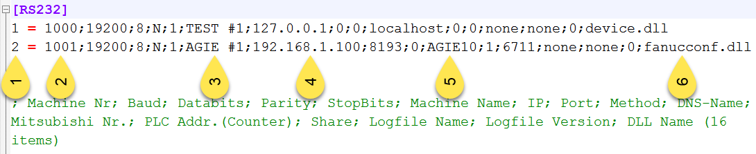
In section [RS232] of CNCnetPDM.ini one device is configured:
Means, CNCnetPDM uses your PC as remote device also (127.0.0.1 and localhost), Device driver is device.dll a simulation that driver creates random values for all items.
Optional: To create an additional device simply copy and paste the first line, change the sequential number of the device (1), assign a new unique device number (2) and name (3). Change IP-Address (4) or DNS Hostname (5). If you’re using one of the controller specific device drivers change device.dll to the name of the driver, here fanucconf.dll (6). For other entries please see the description of the respective driver.
For a new setup CNCnetPDM automatically creates entry ‘StartOffline = 1’ in sections [OPC UA Server], [MTC Adapter] and [Connect] of CNCnetPDM.ini. In this mode the program does not automatically start it's OPC UA Server, the MTConnect Adapter or a database connection.
If you adjusted CNCnetPDM.ini start CNCnetPDM again (see 4.) and double click CNCnetControl, the GUI shows your connected devices on the left (1) and the incoming data on the right (2)