The CNCnetPDM Standard OPC UA device driver allows reading, writing and monitoring of machine-, process- and quality data from devices that run any OPC UA compliant server. Reading and monitoring can be performed in solicited (time controlled) or unsolicited (event driven) mode.
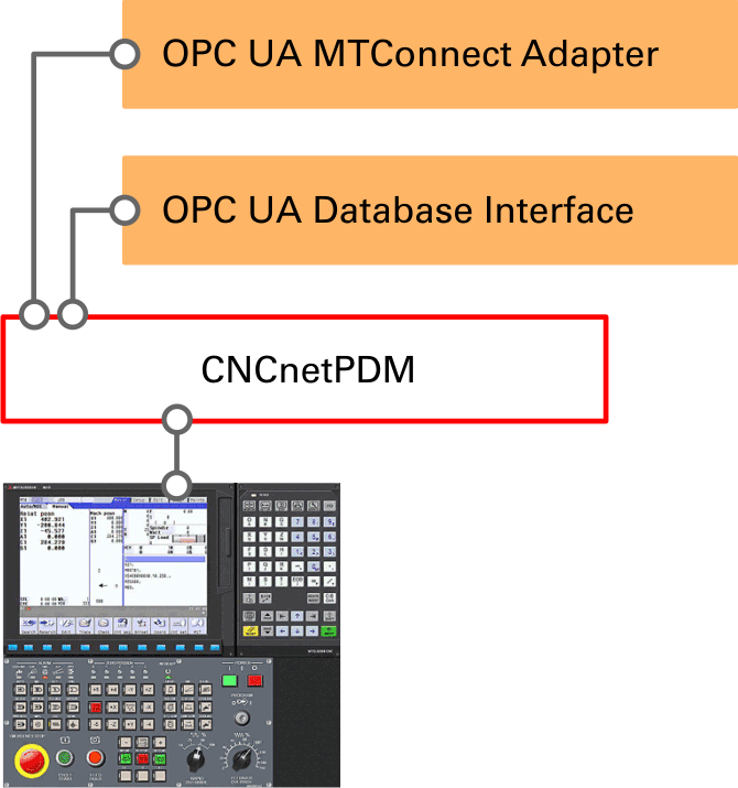
CNCnetPDM OPC UA IoT Interfaces
The OPC UA MTConnect Adapter enables access to machines with an OPC UA Server by any MTConnect compatible application
The OPC UA Database Interface allows output of data from machines with an OPC UA Server to various SQL Databases
Enables simultaneous communication with multiple OPC UA Servers by a single instance of CNCnetPDM
Different controller types (e.g. Fanuc, Heidenhain, Sinumerik) can be mixed within one service instance
Outputs data to various databases, MTConnect compatible programs or your own applications (f.i. with our Free Open Source Client)
Allows definition of individual sets of data acquisition items on a per-machine basis
PREREQUISITES
Please make sure that your device is properly setup and you can communicate with it by our utility tool CNCnetPDM OPC UA Client
Microsoft .NET 4.5.1 has to be installed on your PC
Firewall at your PC has to be switched off or an exception for the TCP port the OPC UA server uses (Default: 4840) has to be added, check access to this port with our Device Port Scanner
Download the CNCnetPDM Standard OPC UA device driver, extract all content of OPC_UA_Device_Driver.zip into the folder where you have CNCnetPDM installed.
Open CNCnetPDM.ini with a text editor
In section [GENERAL] set AcquisitionMethod = 1 to read data from the OPC UA server by polling it in a time interval (solicited messaging). For reading based on events at the OPC UA server (unsolicited messaging) set AcquisitionMethod = 2.
For solicited messaging set PollInterval to the interval (seconds) for polling data from the device.
For unsolicited messaging set PollInterval to the interval (seconds) for checking if the device is connected (alive).
In section [RS232] add a new device as described in the quick start guide point 7. Change the line as follows: 2 = 1001;19200;8;N;1;DEVICE #2;192.168.1.100;0;2;DNS Hostname;0;0;none;none;1;opcua451.dll
Adjust IP Address or DNS Hostname according to the setup of your device.
If you use unsolicited messaging change the number before DNS-Hostname to 2. Any other number switches the driver to solicited messaging.
The number before opcua451.dll defines how the default INI file for the device will be created: 0 creates an INI file for devices that use namespace index 4 (Numeric) like PILZ PLCs or GF AGIE Lasers. 1 creates an INI file for devices that use namespace index 2 (String) like Siemens PLCs or Sinumerik CNCs.
Note: The CNCnetPDM OPC UA Client outputs the namespace used by your device if you click on a node in the OPC UA browser and check the value for namespace index in the right area.
USAGE
Start CNCnetPDM, foreground program is sufficient (Start thread)
CNCnetPDM automatically copies the original opcua451.dll and appends the machine number as configured in the INI file, e.g. opcua451_1001.dll for machine 1001
In addition an INI file with the same name is automatically created by the device driver, e.g. opcua451_1001.ini for machine with device number 1001
Stop CNCnetPDM
Open the device INI file with a text editor and adjust all values in sections [GENERAL] and [SECURITY] as described in chapter ‘ADJUST ITEMS’
Start CNCnetPDM again
Double click CNCnetControl, if your device name is SINUMERIK #1 the output should be similar to the one below:
FIG 1: CNCnetControl (OPC UA device driver)
Here the machine (1) shows up as connected (2) which is good. On the right side (3) you see the acquired data:
The line starting with O contains items defined in the INI file of the device that should be output to section 1. If you didn’t change the INI file you get something like the following:
Every item has a description (Tag name) followed by its value (Tag value). All descriptions and values are delimited by pipe ‘|’ symbols. This allows CNCnetPDM to create database records or MTConnect output for every item.
DEFAULT TAG NAMES
For devices that use namespace index 2 (String) e.g. Sinumerik CNC the initially configured items are:
ID
NAME
DESCRIPTION
0
AUTOM
Automatic mode (numeric)
1
PRGST
Program status (numeric)
2
PARTS
Part counter (numeric)
3
STATN
OEE Device state (numeric)
4
STATT
OEE Device state (text)
5
MODEN
Device mode (number)
6
MODET
Device mode (text)
7
PRGSN
Program state (number)
8
PRGST
Program state (text)
9
PRGMN
Name of the selected program
10
STOPC
Stop condition
11
CHANS
Channel status
12
TOOLN
Tool number
13
SPDSP
Spindle speed
14
OVRSP
Override spindle percent
15
FEEDR
Actual feed rate
16
OVRFD
Override feed
17
PARTC
Actual part count
18
PARTR
Required parts
19
MFUNC
Active M functions
20
RVAR1
Value of R variable 1
21
RVAR2
Value of R variable 2
FIG 2: IDs, names and description of items (Devices that use namespace index 2)
For devices that use namespace index 4 (Numeric) e.g. GF AGIE Laser or PILZ PLCs the initially configured items are:
ID
NAME
DESCRIPTION
0
UMODE
Unit mode (numeric)
1
USTAT
Unit state (numeric)
2
ORDER
Order relation (numeric)
3
STATN
OEE Device state (numeric)
4
STATT
OEE Device state (text)
5
MODEN
Device mode (number)
6
MODET
Device mode (text)
7
PRGSN
Program state (number)
8
PRGST
Program state (text)
9
PRGMN
Actual program name
10
PRGFN
Actual program file
11
LPRGN
Last program name
12
LPRGF
Last program file
13
MSG
Unit message, German
14
MSG
Unit message, English
15
ACRTM
Actual planned runtime
16
LSRTM
Last planned runtime
17
TMPRD
Total actual production time
18
TMSET
Total actual setup time
19
TMBUS
Total actual busy time
20
TMDEL
Total actual delay time
21
TMPRC
Total actual processing time
FIG 3: IDs, names and description of items (Devices that use namespace index 4)
SETUP BACKGROUND SERVICE
To setup a CNCnetPDM background service proceed as follows:
Right click CNCnetPDM, select ‘Run as Administrator’
Click button [Install]
Check ‘Automatic Startup’ if the service should start automatically
In dropdown field ‘Depends on service’ you can select a service that has to be started before CNCnetPDM starts (e.g. a database service)
Leave all fields in section ‘Service Account’ blank.
Click button [Ok], the dialog closes.
You can now click button [Start] to manually start the service.
This device driver enables to dynamically add, group, enable or disable items and change their names. The INI file automatically created by the device driver for every machine contains sections that allow you to control its behavior.
SECTION [GENERAL]
This section contains information about global parameters used by the driver on startup.
‘Commands’ defines the number of OPC commands you’d like to execute, maximum value = 30.
‘Server port’ defines the TCP port number of the OPC UA server at the device, typically 4840.
‘Sampling rate ms’ sets the sampling rate for unsolicited messaging, default = 500, minimum = 100.
‘Operation timeout ms’ defines the time after which the driver assumes that the device is not alive and disconnects.
‘Namespace index’ is the numeric namespace index used by the OPC UA server.
‘Identifier type’ is the identifier type used by the OPC UA server, ‘String’ or ‘Numeric’.
‘Username’ and ‘Password’ define the credentials that the driver uses to access the OPC UA server if anonymous access is not used
‘No authentication’ can be set to 1 if the driver should use anonymous, non-secure access to the OPC UA server, default 0.
‘Server type’ defines how the driver detects OEE machine states, set this to 1 for Sinumerik CNCs.
SECTION [SECURITY]
This section contains information about the OPC UA security mode and policy of the endpoint that the driver should access.
‘Security mode’ can either be None, Sign or SignAndEncrypt.
‘Security policy’ can either be None, Basic128Rsa15, Basic256 or Basic256Sha256.
Note: Please use the security mode and policy as detected by the CNCnetPDM OPC UA Client for your device.
OPC ITEMS
OPC Items you query are organized in sections e.g. [2]. Every section contains entries where you can define names and parameters for a specific OPC item. Unless otherwise instructed do NOT change sections [0] and [1].
Description of the numeric sections:
Entry
Description
[0]
Section identifier, numbers starting with 0 are queried
Active
If you set this to 0 the command is not executed
Name
A short name (max 5 characters) to describe the item e.g. STATN for status number
Comment
A comment that describes the command (optional)
Command
OPC command to be executed e.g. ‘/Channel/State/progStatus’ for identifier type ‘String’ or ‘6112’ for identifier type ‘Numeric’. The command ‘cnc_oeestate’ executes several OPC commands and calculates output relevant for OEE, see section ‘Output item’ and chapter ‘Commands’ below.
Output item
For normal OPC commands this is NOT needed. Only for command ‘cnc_oeestate’ you can enter the values described in chapter ‘Commands’ below.
Output section
You can output data to 3 sections that may contain up to 256 characters. 1 goes to section ‘O’, 2 to ‘A’ and 3 to ‘F’. If data in one section exceeds the maximum length you can send items to a different section. Make sure you have entries CollectOrders, CollectFeeder and CollectQuality enabled (=1) in CNCnetPDM.ini.
FIG 4: Description of a device INI file section
Note: To change commands, switch items on or off or alter its name while CNCnetPDM is running open the INI file with a text editor such as notepad, make the desired changes and save the file. To apply the changes immediately you can click on the machine in CNCnetControl on the left side followed by clicking buttons ‘Close’ and ‘Open’ above the section ‘Devices’.
COMMANDS
Here you can find information about commands and output items that can be used with this driver. In general you can use all OPC UA items output by the CNCnetPDM OPC UA Client with the driver. Also see the ‘Parameter Manual’ of your controller for details or contact us if you need help.
Command cnc_oeestate
This special command is not a real OPC item like ‘/Channel/State/progStatus’. It uses the output of command[0] = ‘Device Mode’ and command[1] = ‘Program State’ to calculate output relevant for OEE. It also translates numeric output of specific OPC queries into text.
COMMAND
OUTPUT ITEM
NOTES
cnc_oeestate
statenumber
Numeric OEE state of the device (2 = producing, 3 = manual, 4 = interrupted, 5 = error)
cnc_oeestate
statetext
State of the device as text (producing, manual, interrupted, error)
cnc_oeestate
modenumber
Numeric running mode of the controller (0 = JOG, 1 = MDA, 2 = AUTO)
CNCnetPDM for OPC UA servers also supports writing and changing of data on these devices from a remote PC. Although writing of ALL writable OPC items is supported it is highly recommended to start with simple commands like changing ‘R variables’. In case you access the OPC UA server of a Siemens Sinumerik controller you can proceed as follows:
With an unmodified INI file for a device that uses identifier type ‘String’ CNCnetPDM queries two ‘R variables’, section [20] = ‘R variable 1’, section [21] = ‘R variable 2’. To change the value of these 2 variables CNCnetPDM has to be running and you should see data for RVAR1 and RVAR2 via CNCnetControl, section ‘F’.
To change the value of a parameter first click on the device in the left area (1). Then click on button [Command] (2). In the drop down box below number (3) select or input 21. Enter a new numeric value into the text box below command text (4) here 1500.33. Click button [OK] (5). You can see the new value in the ‘Device Data’ area in the right pane.
FIG 6: Change R-Variable on Sinumerik controller with OPC UA server
All successful write actions and errors are written to the device’s log file in subfolder \log.
TIPS
For correct setup of the CNCnetPDM OPC UA device driver it is highly recommended to start with the CNCnetPDM OPC UA Client and use its output to define correct commands in your device INI file.
To get correct output of OEE device states please make sure that you use a command for section 0 in your device INI file that outputs the device mode and one for section 1 that outputs the program state.
If OEE device states are still incorrect you can set CollectStates = 0 in CNCnetPDM.ini and calculate the values by your application program. To do so you can use different commands for section 0 and 1 and define an output section other than 0 for them.
If your device does not output part counter values set Active = 0 for section 2 in your device INI file.
OPC items on OPC UA servers that use the ‘String’ identifier such as Siemens Sinumerik are case sensitive, for example NC program status has to be queried with /Channel/State/progStatus, if you use /Channel/State/PROGSTATUS you get an error.
If you want to add additional items (up to 30 in total) first adjust the number of commands in section [GENERAL]. Then, copy and paste the last numeric section and do not forget to adjust the section number and its content!
In case you use the device driver in unsolicited mode and you query items that change very fast e.g. Axis position it is recommended to use higher values for the sampling rate.
LICENSING
This device driver requires the most recent version of CNCnetPDM and also works with a free license. However, in this mode you only get output for the first item configured in your INI file. With a valid license you are able to output the result of up to 30 functions per reading cycle, see licensing for details.
TROUBLESHOOTING
The device driver writes a log file entry for any communication issue to the log file of the device. The file can be found in subdirectory \log of your CNCnetPDM program folder. The file format for the log file is log_ + device number + _ + date.txt. Please check this file first if you observe an issue.
If the machine shows a red icon, state disconnected and you get just output E = 0 the machine is not reachable at all. This has nothing to do with the device driver, the controller is switched off, it’s a network issue or DNS Hostname or IP Address is wrong.
If the machine shows a green icon, state connected but you just get output E = 1 the machine is reachable but the controller does not respond to commands, check your controller setup and the parameters used in section [RS232] of CNCnetPDM.ini. Please use the tool CNCnetPDM OPC UA Client to check if you can access the OPC UA server of the device.
If you do get numeric device states but not any of the preconfigured items please make sure that entries CollectOrders, CollectQuality and CollectFeeder are set to 1 in section [General] of CNCnetPDM.ini.
If connection to your device succeeds but you do not get any output please check that the value for AcquisitionMethod in section [GENERAL] of CNCnetPDM.ini matches the setup of your device in section [RS232]. For AcquisitionMethod = 2 you have to use number 2 before DNS-Hostname in the line that defines the device.
If you defined an incorrect device INI file or messed it up you can simply delete it and switch the device off and on via CNCnetControl. The INI file then gets automatically recreated.
If specific items are not acquired check first with CNCnetPDM OPC UA Client if you can access the desired OPC UA node. Also make sure that the numeric section of the item in the device drivers INI file is activated and has an entry for ‘Name’, inactive or items with empty names are not acquired. Also check that you didn’t misspell entries for command and output item in your device driver INI file.
UPGRADE DRIVER
If you already have a previous version of the driver opcua451.dll installed and would like to upgrade to the most recent version proceed as follows:
Stop any CNCnetPDM background service or foreground program that uses the device driver
Extract all content of OPC_UA_Device_Driver.zip into the folder where you have CNCnetPDM installed, overwrite the existing files
Delete all opcua451_NNNN.dll and ClientAPIUA451_NNNN.dll (NNNN = machine number) files. If you already have created adapted INI files for specific devices do NOT delete the opcua451_NNNN.ini files
After restarting CNCnetPDM upgraded device driver versions for all machines are automatically created
Stop any CNCnetPDM background service or foreground program that uses the device driver
Extract all content of OPC_UA_Device_Driver.zip into the folder where you have CNCnetPDM installed
With a text editor change all occurrences of sinumerikua.dll to opcua451.dll in section [RS232] of CNCnetPDM.ini
Change the value before opcua451.dll to 1 e.g.: ;1;opcua451.dll
Only if you’d like to switch to unsolicited (event driven) messaging change the value before DNS Hostname to 2 f.i.: ;2;localhost;
After starting CNCnetPDM new INI files for all machines defined in section [RS232] of CNCnetPDM.ini will be created automatically e.g. opcua451_NNNN.ini (NNNN = machine number)
Stop CNCnetPDM
Change the values in sections [GENERAL] and [SECURITY] in the new INI file according to the output of the CNCnetPDM Standard OPC UA Client
Replace all sections [0] -> [N] in this new INI file with the sections from your sinumerikua_NNNN.ini file
Save the new INI file
Start CNCnetPDM
Privacy notice
This website uses cookies. By continuing to use it you agree to our privacy policy.