The CNCnetPDM Okuma MTConnect device driver allows monitoring of machine- process- and quality-data in near real time from Okuma machines with OSP P controllers version OSP-P 100 or higher.
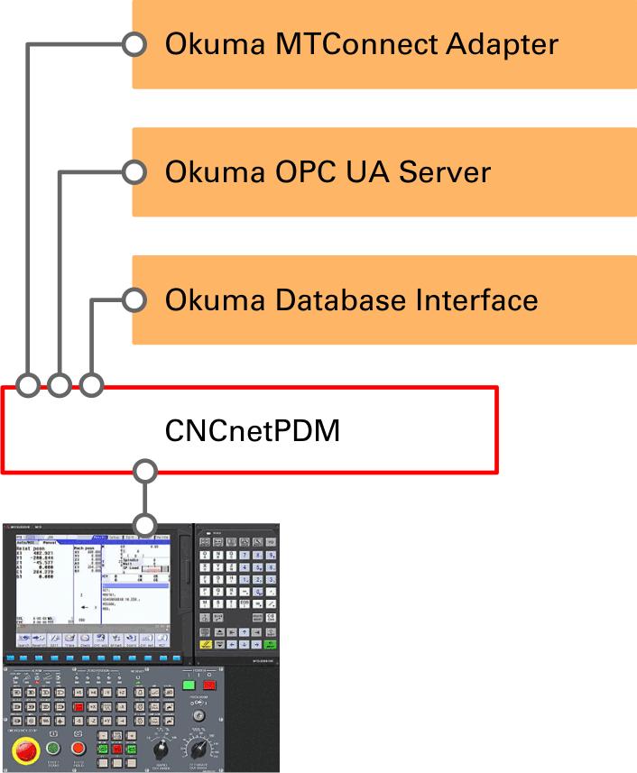
CNCnetPDM OKUMA IoT Interfaces
The Okuma MTConnect Adapter enables access to Okuma machine data by any MTConnect compatible application
The Okuma OPC UA Server adds an OPC UA compliant server to any Okuma Lathe, Machining Center or Grinder
Important note: This driver uses unsolicited messaging. If you already have CNCnetPDM running on your PC with a device driver that works with solicited messaging (e.g. Fanuc, Heidenhain) you have to create a separate instance of the service for your Okuma machines.
This device driver requires at least Version 8.0.0.0 of CNCnetPDM and also works with a free license. However, in this mode the driver only outputs the first two items you defined in section [MTC TAGS]. With a valid license you are able to output up to 160 items from the controller, see licensing for details.
SETUP CNCNETPDM
Download CNCnetPDM (at least Version 8.0.0.0 is needed) and install it as described in the quick-start-guide.
Edit CNCnetPDM.ini (or CNCnetPDM+Instance.ini) and modify it as follows, leave all other values at their default:
Section [GENERAL]:
AcquisitionMethod = 2 This driver uses unsolicited (event driven) communication.
PollInterval = 10 Define the interval (number of seconds) for checking if the device is connected.
ReconnectAfter = 3 Define after how many successful connection checks CNCnetPDM should try to reconnect to the controllers Okuma MTConnect Adapter if the device changed its state from disconnected to connected. As the machine needs some time to start up the combination of PollInterval and ReconnectAfter should be long enough e.g. 10 x 3 = 30 sec. For older machines increase this value.
CollectStates = 0
CollectCounters = 0
For initial testing its recommended to set CollectStates and CollectCounters to 0. If you set them to 1 please make sure that you have matching tag names for OEE device states and part counter set up in the respective machine INI file.
Section [RS232]:
If you identify your controller by IP address change it from 127.0.0.1 to its correct address e.g. 192.168.1.100.
If you identify your controller by DNS-Hostname change it from localhost to its correct value e.g. OKUMA_1.
Change 0 after IP address to the port number your controller uses for communication (Default: 7878)
Change the name of the device driver from device.dll to mtcclient.dll
Change the value before mtcclient.dll to a number that matches your Okuma machine type: 2 = Okuma Standard Lathe 3 = Okuma Lathe 2 sides 4 = Okuma Machining Center 5 = Okuma Grinder
CNCnetPDM then automatically creates a suitable device INI file for this specific Okuma machine
A correct example for an Okuma Standard Lathe (=2) would look like:
FIG 1: Definition example of a Okuma machine with MTConnect Adapter in CNCnetPDM.ini
Save CNCnetPDM.ini
USAGE
Start CNCnetPDM, foreground program is sufficient (Start thread)
CNCnetPDM automatically copies the original mtcclient.dll and inserts the machine number as configured in the INI file, e.g. mtcclient_1000.dll for machine 1000.
In addition an INI file with the same name is automatically created by the device driver, e.g. mtcclient_1000.ini for machine with device number 1000.
Double click CNCnetControl, if your device number is 1000 and the device name is OKUMA LS the output should be similar to the one below:
Here the machine (1) shows up as connected (2) which is good. If you receive data from the controllers MTConnect Adapter you can see it on the right side (3).
The line starting with O contains tag name | value pairs from valid tag names as defined in the INI file of the device. If you didn’t change the INI file you get something like the following:
1000 06/21/2026 01:43:41 PM 10000004315 A pmode|AUTOMATIC| 10000000009
Tag name and value are delimited by a pipe ‘|’ symbol. This allows CNCnetPDM to create OPC UA Server or database output for every tag | value pair.
Note: To instruct CNCnetPDM to automatically create a device INI file that matches your Okuma machine type (Standard Lathe = 2, 2-Sides Lathe = 3, Machining center = 4 or Grinder = 5) you can simply edit CNCnetPDM.ini and, in section [RS232], change the value before mtcclient.dll from 0 to 2, 3, 4 or 5. A correct example for an Okuma Standard Lathe would look like: 1 = 1000;19200;8;N;1;OKUMA #1;192.168.1.100; 7878;0;OKUMA_1;0;0; none;none;2;mtcclient.dll. If you already have a mtcclient_nnnn.ini file with incorrect content please rename or delete it before doing so.
The machine specific INI file of the device driver f.i. mtcclient_1000.ini enables to dynamically modify, enable or disable tags that should be acquired from your Okuma controller
It also allows to define the frequency and content of heartbeat commands that have to be sent to the Okuma MTConnect Adapter
In addition you can define the content of responses to heartbeat commands and the number of unsuccessful ping commands after which the device driver automatically reconnects
By setting a tag name and possible values for OEE device states you can output numeric values for these states
'Ping interval' defines interval in seconds for sending heartbeat commands to the Adapter, default 10
'Ping command' defines the content of the heartbeat command to be sent to the Adapter, default * PING
'Pong message' defines the expected content of responses to heartbeat commands sent to the Adapter, default * PONG
'Pong error limit' defines the number of failed heartbeat commands required before the driver automatically reconnects to the Adapter, default 2
'Limit speed' (default 1) allows you to reduce the number of CNCnetPDM read events to 1 per second without loosing data received from the machine. This is highly recommended for Okuma MTConnect Adapters that send new data packets in high frequency down to milliseconds to avoid performance issues and service crashes. Setting 'Limit speed' to 0 disables this feature
'Condition delimiter' defines a single character that delimits fields level, native code, native severity and text for conditions e.g. 'system|FAULT,129,90,INSIDE INTERLOCK AXIS|', default blank ' '
Section [AVAILABILITY]
'Tag name' allows to define a tag name that should be used to determine if the controller connected to its Adapter is up or down (default ‘avail’). Okuma MTConnect Adapters usually provide this tag. For Adapters that do not output this tag you can use any tag name that changes to ‘UNAVAILABLE’ if the controller goes down f.i. ‘pexecution’.
Section [OEE DEVICE STATES]
'Tag name' contains the name of a tag sent by the Adapter (e.g. Okuma: ‘pexecution’) and its possible values for states Producing (2) (default ‘active’), Manual (3) (default ‘stopped’) and Interrupted (4) (default ‘interrupted’). CNCnetPDM automatically reports (0) for devices that are not reachable at all and (1) for reachable devices where the Adapter does not respond.
Section [PART COUNTER]
'Tag name' defines which tag name (e.g. Okuma: ‘ppartcount’) outputs numeric part counts. This enables you to use CNCnetPDM’s cumulative or incremental part counting features that allow detection of part counter reset operations at the controller.
Sections [ERROR1-3]
In these sections you can define tag names and values that indicate a faulted OEE machine state. If, for example the emergency button at the controller is pressed the adapter outputs tag 'estop' with value 'triggered'. If you define this tag name and its value in one of the error sections the device driver outputs OEE machine state 5 in case they are received. If a specific condition e.g. tag name ElectricSystem1_cond should be treated as error it's value typically is 'fault'.
SECTION [MTC TAGS]
Contains a list with MTConnect Adapter input and output tag names and their type (E = event or sample, C = condition). Every line starts with a unique number followed by input and output tag name and type delimited by pipe '|' characters.
Section [MTC TAGS] replaces section [MTC TAG NAMES] of older versions of the driver. If you upgrade from an older version this section is automatically created based on the content of former entries 'Valid tags' and 'Condition tags'.
To exclude a tag insert a semicolon at the start of the line
To translate an input to an output tag name change the text after the first pipe character to the desired value
To change tag type from condition to event or sample change the text after the second pipe character from C to E or vice versa
FIG 2: Exclude and translate Okuma MTConnect tags in INI file section [MTC TAGS]
Notes:
To change the content of this INI file while CNCnetPDM is running open it with a text editor such as notepad, make the desired changes and save the file
To apply the changes immediately without the need to stop CNCnetPDM you can click on the machine in CNCnetControl on the left side followed by clicking buttons ‘Close’ and ‘Open’ above the section ‘Devices’
TROUBLESHOOTING
The device driver writes a log file entry for any communication issue to the log file of the device. The file can be found in subdirectory \log of your CNCnetPDM program folder. The file format for the log file is log_ + device number + _ + date.txt. Please check this file first if you observe an issue.
If the machine shows a red icon, state disconnected the machine is not reachable at all. This has nothing to do with the device driver, the controller is switched off, it’s a network issue, DNS Hostname or IP Address is wrong. With CollectStates = 1 set in CNCnetPDM.ini you get output E 0 in regular intervals in this case.
If the machine also shows a red icon, state disconnected but you do not see any output even there is activity at the controller the machine is reachable but the MTConnect device driver is not able to connect to the Adapter at the controller. In this case, check your controller setup and the parameters used in section [RS232] of CNCnetPDM.ini. Please use the tool Okuma MTConnect Adapter Analyzer to check if you are able to connect to the Adapter and get data. With CollectStates = 1 set in CNCnetPDM.ini you get output E 1 in regular intervals in this case.
If you do not get any tag data please make sure that entries CollectOrders, CollectQuality and CollectFeeder are set to 1 in section [General] of CNCnetPDM.ini.
If you incorrectly define an event or sample tag as condition e.g. 'execution|execution|C' the driver treats the following 5 input items as condition tag values which leads to missing and incorrect output.
If you incorrectly define a condition tag as event or sample e.g. 'servo_cond|servo_cond|E' only the first condition value is output and the following 4 values get lost.
In case you have machines connected that send new data packets in high frequency and you experience performance issues or occasional service restarts make sure that 'Limit speed' in section [GENERAL] is set to 1.
UPGRADE DRIVER
If you already have a previous version of the driver installed and would like to upgrade to the most recent version proceed as follows:
Stop any CNCnetPDM background service or foreground program that uses the device driver
Extract all content of mtcclient_dll.zip into the folder where you have CNCnetPDM installed, overwrite the existing files.
Delete all mtcclient_NNNN.dll (NNNN = machine number) files. If you already have created adapted INI files for specific devices do NOT delete the mtcclient_NNNN.ini files.
After restarting CNCnetPDM upgraded device driver versions for all machines are automatically created.
Privacy notice
This website uses cookies. By continuing to use it you agree to our privacy policy.