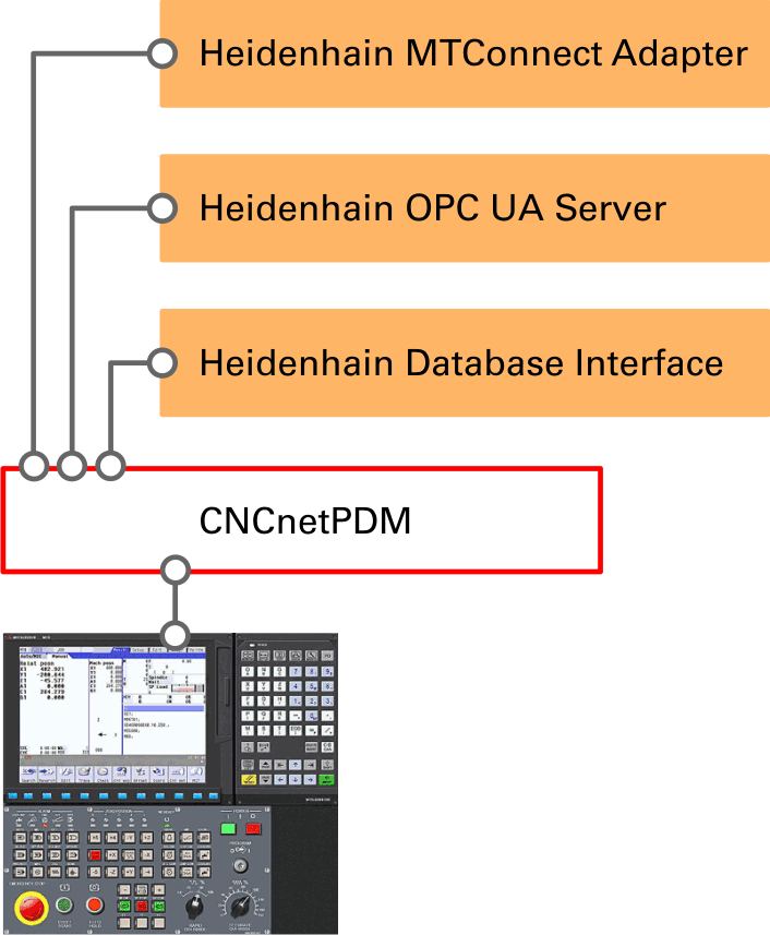
This highly configurable Heidenhain IIoT adapter for CNCnetPDM enables you to monitor machine-, process- and quality data from machines with Heidenhain controllers from TNC 426 up to TNC 7, see adapted controllers. It also allows remote control by its ability to set or change Programmable Logic Controller (PLC) data values and machine parameters.
The Heidenhain MTConnect Adapter enables bidirectional access to Heidenhain CNC devices by any MTConnect compatible application
The Heidenhain OPC UA Server adds OPC UA Server functionality to machines with Heidenhain controllers
The Heidenhain Database Interface allows output of data from machines with Heidenhain controllers to various SQL Databases
You can dynamically define your own set of commands (up to 32 for reading and 7 for writing) that can be enabled and disabled on a per machine basis by an INI file that is automatically created with reasonable default values. This INI file also allows to define individual tag names for every output value.
CNCnetPDM fully supports password and key based secure communication, supported from TNC 320 up to TNC 7
For newer controls (TNC 320 -> TNC 7) CNCnetPDM allows to read and write PLC data by usage of symbolic PLC names
For bidirectional communication between machines with Heidenhain controllers connected to CNCnetPDM and your applications you can use our free Open Source Client (C-Sharp)
FIG 1: Heidenhain TNC 640 Operator panel
PREREQUISITES
Make sure that you have an Ethernet network connection between your PC and the machine and get data, use our HeidenhainData utility to do so.
If you use a firewall and secure communication (>= TNC 320) add an exception for TCP port 22 (SSH) to your Firewall (in both directions) or, for non-secure (legacy) communication add an exception for port 19000.
DOWLOAD DRIVER
LICENSING
This device driver requires the most recent version of CNCnetPDM and also works with a free license. However, in this mode output is limited to the OEE machine state of your device. With a valid license you are able to output the result of up to 32 commands per reading cycle, see licensing for details.
Download the Heidenhain driver and extract all files into the folder where you have CNCnetPDM installed.
Edit CNCnetPDM.ini and add a new device as described in the quick start guide point 7. If you already have an entry in section [RS232] for a machine you can simply copy and paste this line and change its content. Change the line as follows:
FIG 2: Configure Heidenhain device driver in CNCnetPDM.ini
For machines with Heidenhain controllers the following 2 parameters are important:
Right to the IP Address of the controller (here 192.168.1.212) enter number 19000 (=port)
Change the driver name to heidenhain.dll
USAGE
Start CNCnetPDM, foreground program is sufficient (Start thread)
CNCnetPDM automatically copies the original heidenhain.dll and appends the machine number as configured in the INI file, e.g. heidenhain_1000.dll for machine number 1000.
In addition an INI file with the same name is automatically created by the device driver, e.g. heidenhain_1000.ini for machine number 1000.
With CNCnetPDM started double click CNCnetControl, if your device number is 1000 and the device name is 'Cheto IXN W11' the output should be similar to the one below:
FIG 3: CNCnetControl (Heidenhain TNC 640)
Here the machine (1) shows up as connected (2) which is good. On the right side (3) you see the acquired data:
The line starting with O contains items defined in the INI file of the device that should be output to section 1. If you didn’t change the INI file you get something like the following:
Every output item has a tag name followed by its tag value. All names and values are delimited by pipe ‘|’ symbols. This allows CNCnetPDM to create a database record, MTConnect or OPC UA output for every item.
With an unmodified INI file the initial configured and activated items are:
Id
Name
Description
Active
1
PARTC
Part counter value
No
2
STATN
OEE Device state (numeric)
Yes
3
STATT
OEE Device state (text)
Yes
4
MODEN
Device mode (number)
Yes
5
MODET
Device mode (text)
Yes
6
PRGSN
Program state (number)
Yes
7
PRGST
Program state (text)
Yes
8
PRGMN
Name of the selected program
Yes
9
PRGCU
Name of the active program (if any)
Yes
10
BLKCU
Actual block number
Yes
11
ERRCL
Error class (iTNC 530 only)
No
12
ERRGR
Error group (iTNC 530 only)
No
13
ERRNO
Error number (iTNC 530 only)
No
14
ERRTX
Error text (iTNC 530 only)
No
15
TOOLN
Tool number (>= iTNC 530)
Yes
16
TOOLI
Tool index (>= iTNC 530)
Yes
17
TOOLA
Tool axis (>= iTNC 530)
Yes
18
TOOLL
Tool length (>= iTNC 530)
Yes
19
TOOLR
Tool radius (>= iTNC 530)
Yes
20
OVRFD
Override feed %
Yes
21
OVRSP
Override speed %
Yes
22
OVRRP
Override rapid %
Yes
23
AXESP
Position of axes
Yes
24
CUTTP
Position of cutter
Yes
25
PLCM1
Read marker value from the PLC
No
26
PLCB1
Read byte value from the PLC
No
27
PLCW1
Read word value from the PLC
No
28
PLCD1
Read dword value from the PLC
No
29
P3515
Read machine parameter value (>= iTNC 530)
No
30
DATA1
Read data from the tool table (iTNC 530 only)
No
31
WMARK
Write marker value to the PLC
No
32
WBYTE
Write byte value to the PLC
No
33
WWORD
Write word value to the PLC
No
34
WDWRD
Write dword value to the PLC
No
35
WPARA
Write machine parameter value
No
36
PLCS1
Read PLC data by symbolic name (>= TNC 320)
No
37
WSYMN
Write PLC data by symbolic name (>= TNC 320)
No
38
PLCST
Read string value from the PLC (>= iTNC 530)
No
39
WSTRN
Write string value to the PLC (>= iTNC 530)
No
FIG 4: Ids, names, description and initial activation state of items
ADJUST MACHINE INI FILE
This device driver enables to dynamically add, group, enable or disable items and change their names. The INI file automatically created by the device driver for every machine contains sections that allow you to control its behavior.
This section contains information about global parameters used by the driver on startup.
Connection Delay (Optional) allows to specify a time period in milliseconds (0 - 5000) between connection to the controller and start of communication, default = 0.
Commands defines the number of all commands you’d like to use for reading and writing, maximum value = 37.
No DNC Option enables, if set to 1, data acquisition from newer controllers (iTNC 530 -> TNC 7) that do not have DNC Option 18 activated: How-to instructions, default = 0.
Legacy PLC allows, if set to 1, to automatically convert PLC Byte, Word or DWord output from legacy controllers like TNC426 or TNC430 to a proper format. Please set Legacy PLC = 1 in case PLC output differs from the values you see at the controller, default = 0.
PLC Password can be used to enter a PLC Password or Code Number if PLC access is restricted by a password or code number, default = empty.
Symbolic PLC Address Names name of the file with symbolic PLC address name definitions of your machine (iTNC 320 -> TNC 7 only) in subfolder \plcdatamarker of CNCnetPDM, see symbolic PLC names, default PlcDataMarker.txt
MARKERS
This section contains addresses of PLC Markers that are automatically used to identify the operation mode and program state of your machine if the controller does not support high-level language commands to acquire this information. Needed for older TNC426, 430 devices and all newer controllers that do not have DNC Option 18 activated.
PLC Marker Command (default plcmarker) allows you to read markers from various PLC areas. This entry only has to be adjusted for data acquisition from controllers that do not have DNC Option 18 activated: How-to instructions.
SSH
In this section you can define parameters that should be used for secure SSH communication (>= TNC 320)
Use Secure Communication enables secure communication: 1 = yes, 0 = no, default = 0
Public Key public key file for secure communication, default = cert\user@cncnetpdm.pub
User Name SSH user name for secure communication, default = user
Password SSH password for secure communication, default = user
NUMERIC SECTIONS [1 - 39]
Items for reading and writing are organized in numeric sections e.g. [2]. Every section contains entries where you can define names, commands and parameters for a specific item.
Section identifier, numbers from 1 to 30, 36 and 38, if active, are queried when reading, 31 to 35, 37 and 39 can be used for writing
Active
If you set this to 0 the command is not executed when reading data from the device. This setting has no effect on commands for writing
Name
A short name (max 5 characters) to describe the item e.g. STATN for status number
Comment
A comment that describes the command (optional)
Command
Command to be executed e.g. cnc_oeestatus for the command group that contains running status. To change a command select an available command, copy it and paste it into the INI file.
Input parameter 1
For some commands input parameters can be used to set an input parameter (PLC), control output formatting e.g. program name with or without path or a divisor for an output value, see the command description.
Input parameter 2
Necessary for some commands, usually an optional divisor for PLC output (default = -1)
Output item
Some commands have sub-commands that enable you to define a specific item to be output by the driver e.g. statenumber from cnc_oeestate outputs the device state.
Output section
You can output data to 3 sections that may contain up to 256 characters. 1 goes to section ‘O’, 2 to ‘A’ and 3 to ‘F’. If data in one section exceeds the maximum length you can send items to a different section. Make sure you have entries CollectOrders, CollectFeeder and CollectQuality enabled (=1) in CNCnetPDM.ini.
FIG 5: Description of a device INI file section
Note: To change commands, switch items on or off or alter its name while CNCnetPDM is running open the device INI file with a text editor, make the desired changes and save the file. To apply the changes immediately you can click on the machine in CNCnetControl on the left side followed by clicking buttons ‘Close’ and ‘Open’ above the section ‘Devices’.
COMMANDS
Below you can find commands and output items that can be used with this driver.
Note: Items with note ‘iTNC530 only’ are only supported by iTNC 530 controls. Please do not set them to active for newer controllers from TNC 320 up to TNC 7.
For TNC 426 and 430 most items can be acquired by using plcmarker, plcbyte, plcword or plcdword commands. Please contact us for detailed instructions.
Command
Output Item
Notes
cnc_oeestate
statenumber
Numeric OEE state of the device (2 = producing, 3 = manual, 4 = interrupted, 5 = error)
cnc_oeestate
statetext
State of the device as text (producing, manual, interrupted, error)
cnc_oeestate
modenumber
Numeric running mode of the controller (0 = Manual, 1 = MDI, 2 = Pass Reference, 3 = Single Step, 4 = Automatic, 5 = Undefined)
Selected program, if you set ‘Input parameter 1’ to 1 only the program name without path is output
ncprogram
NameActiveProgram
Active (running) program, if you set ‘Input parameter 1’ to 1 only the program name without path is output
ncprogram
BlockNr
Actual program block executed
error
ErrorClass
Error class if any (iTNC530 only)
error
ErrorGroup
Error group if any (iTNC530 only)
error
ErrorNumber
Error number if any (iTNC530 only)
error
ErrorText
Error text if any (iTNC530 only)
tool
ToolNr
Tool number (>= iTNC530)
tool
ToolIndex
Tool index (>= iTNC530)
tool
ToolAxis
Tool axis (>= iTNC530)
tool
ToolLen
Tool length (>= iTNC530)
tool
ToolRad
Tool radius (>= iTNC530)
override
Feed
Feed override (percent)
override
Speed
Speed override (percent)
override
Rapid
Rapid override (percent)
axes
Position of axes. By setting ‘Input parameter 1’ to a positive value you can limit the number of axes that should be output (default 5)
cutter
Cutter position. By setting ‘Input parameter 1’ to a positive value you can limit the number of cutters that should be output (default 5)
plcmarker
Read PLC Marker value (0 or 1). ‘Input parameter 1’ defines the numeric PLC address
plcbyte
Read PLC Byte value. ‘Input parameter 1’ defines the numeric PLC address. ‘Input parameter 2’ can be used if the output value has to be divided, use 1 for no division.
Reads a machine parameter e.g. 3515. ‘Input parameter 1’ defines the parameter to be read.
data
\\TABLE\\TOOL\\T\\1\\DOC
Output item = item to be queried (iTNC 530 only). In this example a value from the tool table is read
writeplcmarker
Command for writing PLC marker values (0 or 1). PLC address and value to be written have to be contained in the command from your application
writeplcbyte
Command for writing PLC byte values, PLC address and value from your application.
writeplcword
Command for writing PLC word values, PLC address and value from your application. PLC address has to be divisible by 2!
writeplcdword
Command for writing PLC dword values, PLC address and value from your application. PLC address has to be divisible by 4!
writeparameter
Write value for a machine parameter to the device. Machine parameter name, desired value and flag have to be contained in the input command
plcsymname
APICHN[0].NN_CHNPROGFEEDMINUTE
Reads PLC data by symbolic name (>= TNC 320)
writeplcsymname
Writes PLC data by symbolic name (>= TNC 230)
plcstring
Read PLC String value. ‘Input parameter 1’ defines the row number of the string in the PLC string table
writeplcstring
Command for writing PLC String value from your application.
FIG 6: Description of available command groups and output items
TIPS
If you want to add additional items (up to 39 in total) first adjust the number of commands in section [GENERAL]. Then, copy and paste a complete INI file section and adjust the section number and its content.
TEST WRITING OPERATIONS
It is highly recommended to test any writing operation to Heidenhain controllers before using them in a production environment with the device driver. For verification that you can access and write PLC data or machine parameters you should first use the GUI tool HeidenhainPlcData. To test with the device driver proceed as follows:
In CNCnetControl select the device at the left side
After clicking on button [Cmd], an additional dialog opens.
Select the command number followed by 3 items delimited by pipe symbols ‘|’. If you’re using the standard device INI file you can enter:
Item
Nr.
Input
Comment
Marker
31
1|1|0
Sets Marker value at address 1 to 1
Byte
32
1|1|0
Sets Byte value at address 1 to 1
Word
33
2|1|0
Sets Word value at address 1 to 1
DWord
34
24|1|0
Sets Dword value at address 24 to 1
Parameter
35
3515|5001|0
Sets parameter value of parameter 3515 to 5001
Symbolic name
37
DG_GEAR_RANGE_OLD[0]|1|0
Sets value of symbolic PLC name DG_GEAR_RANGE_OLD[0] to 1
String
39
126|TEST|0
Sets PLC String value at PLC string table row number to TEST
FIG 7: Format of writing commands
The first item in column input is the numeric PLC address, symbolic PLC address name or machine parameter followed by the desired value and a flag. Flag only has an effect on machine parameters. Possible values: 0 = persistent, 1 = temporary, 2 = persistent on reset.
To verify the result you can either define sections to read these values in your machine INI file or check with HeidenhainPlcData.
TROUBLESHOOTING
The device driver writes a log file entry for any communication issue to the log file of the device. The file can be found in subdirectory \log of your CNCnetPDM program folder. The file format for the log file is log_ + device number + _ + date.txt. Please check this file first if you observe an issue. Deactivate commands with issues by setting them to ‘Active = 0’.
If the machine shows a red icon, state disconnected and you get just output E = 0 the machine is not reachable at all. This has nothing to do with CNCnetPDM, it’s a network issue, DNS Hostname or IP Address is wrong.
If the machine shows a green icon, state connected but you just get output E = 1 the machine is reachable but the controller does not respond to commands, check your controller setup and the parameters used in CNCnetPDM.ini (esp. port number).Please use the tool HeidenhainData to check if the machine replies to commands.
If you use SSH Username/Password authentication and the log file contains: SSH Authentication by username - password failed check your controller setup and make sure that the machine's INI file uses correct data.
If you use SSH Key File authentication and the log file: SSH Authentication by public - private key failed check your controller setup and make sure that that the machine's INI file uses correct data including username and password.
If you get numeric device states but not any of the preconfigured items please make sure that entries CollectOrders, CollectQuality and CollectFeeder are set to 1 in section [General] of CNCnetPDM.ini.
If specific items are not acquired check first with HeidenhainData or HeidenhainPlcData that you get output. Also make sure that the numeric section of the item in the device drivers INI file is activated and has an entry for ‘Name’, inactive or items with empty names are not acquired. Also check that you didn’t misspell entries for command and output item in your device driver INI file.
If the machine is equipped with external devices like handling robots, bar feeders or tool magazines and either the external component or CNCnetPDM refuses to work disable (Active = 0) all commands including workpiece counter that access the controls PLC. Connection to TNCs that do not have DNC Option 18 enabled is not possible in this case. By design Heidenhain only allows one connection to the machine's PLC from a remote device.
In case you experience problems with other programs that interact with the controller (like tool control software) while CNCnetPDM is running make sure that you do not use any command that accesses the machine’s PLC for reading or writing.
UPGRADE DRIVER
If you already have a previous version of the driver installed and would like to upgrade to the most recent version proceed as follows:
Stop any CNCnetPDM background service or foreground program that uses the device driver.
Extract all files from heidenhain_dll_9.zip into the folder where you have CNCnetPDM installed, overwrite the existing file.
Delete all existing heidenhain_NNNN.dll (NNNN = machine number) files.
Do not delete the heidenhain_NNNN.ini files.
After restarting CNCnetPDM upgraded device driver versions for all machines are automatically created.
Note: To upgrade to version 9.4.0.0 set Commands = 39 in section [GENERAL] of all existing heidenhain_NNNN.ini file and add the following sections to the end of the INI files: