For Programmable Logic Controllers (PLC) this diagnostic tool allows you to test reading and writing operations. It assists to quickly setup customized PLC device driver INI files for CNCnetPDM. The application can be executed on a PC with MS Windows OS (>= XP SP3) connected to PLCs or any electronic device that supports Modbus TCP protocol (Server mode) via Ethernet.
To test reading and writing operations first make sure that the controller is connected to the network and setup with an IP Address reachable from your PC.
Next, setup the device to allow Modbus access and add at least one Ethernet Modbus Server Connection with a TCP port for remote communication (default: 502). If you plan to access the PLC simultaneously from multiple PCs setup additional connections with subsequent TCP ports, e.g. 503, 504.
Note: If you’d like to work with this program but do not have a PLC you can use FieldTalk’s cost free Modbus slave simulator software diagslave. For a Modbus TCP slave-client that runs on TCP port 502 with Slave Id 9 run it from a command prompt at a local or remote PC with the following arguments:
diagslave -m tcp -o 60 -a 9
SOFTWARE DOWNLOAD
LICENSING
If you have installed CNCnetPDM on your PC with a license other than a ‘free license’ and run this program from the folder where CNCnetPDM is installed you get unlimited functionality. Otherwise you can only Read Bits from a remote device. Please see licensing for details or contact us if you have any questions.
Note: If you like to run this program from a different folder on your PC you can simply copy your CNCnetPDM.ini file to this directory.
SOFTWARE SETUP
Download and extract all contents of modbus_test.zip to a folder on your PC.
In case you use a firewall at your PC or your company network please make sure that there is an exception for the TCP Port your PLC uses (default: 502). You can use our tool Device Port Scanner to check if the device is reachable via this port.
USAGE
READ DATA
Double click ModbusGui
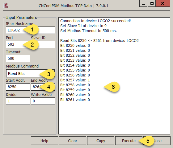
Input IP Address or DNS Hostname of your PLC (1). Slave ID is only required for specific devices, Timeout only has to be increased for very slow network connections, leave at 500 (= 0.5 sec.).
Enter the TCP Port used for communication (2), default 502.
Select one of the available commands (3). Initially ‘Read Bits’ is selected which reads multiple Bit values (0 or 1) from Start to End-Address (4), here from 8250 to 8261.
Clicking on [Execute] (5) shows the result of the operation in the output area (6), here Bit 8257 is set to 1.
FIG 1: Output of ModbusGui (Read Bits)
Commands for reading:
COMMAND
DESCRIPTION
Read Bits
Reads the status (0/1) of multiple bits (aka Coils) from the selected address range. Reading of bits only makes sense if the value at a specific address is maintained by the PLC program, otherwise you just get 0.
Read Input Bits
Reads the status (0/1) of multiple physical digital inputs of the remote device from the selected address range.
Read Registers
Reads the numerical values of multiple holding registers from the selected address range. Values of holding registers read by this function have to be maintained by the PLC program, otherwise the output is 0.
Read Input Registers
Reads the numerical values of multiple physical analog inputs from the selected address range.
FIG 2: Available commands for reading
Note: If needed, output values of register and input registers can be divided by entering a divisor in field ‘Divide’.
WRITE DATA
ModbusGui can also be used to set values of writable bits and registers at a remote device. Input Bits and Input Registers are read only.
To write values to a PLC proceed as follows:
Make sure that you can read values from the desired address or address range.
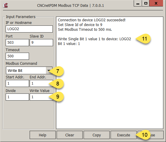
Select one of the available commands for writing, here ‘Write Bit’ (7) and select a target address, here 1 (8). Commands that write single values use ‘Start Address’ as target.
Input the desired value into field ‘Write Value’ (9), here 1.
Click on [Execute] (10).
The result of the writing operation shows up in the right area (11). If needed you can verify the result by executing function ‘Read Bits’.
FIG 3: Output of ModbusGui (Write Bit)
Commands for writing:
COMMAND
DESCRIPTION
Write Bit
Sets the status of a single bit at the selected start address to 0 or 1. Input of values > 1 set the bit to 1, values < 0 set the bit to 0.
Write Bits
Sets the status of a multiple bits in the selected address range to 0 or 1. Input of values > 1 sets all bits to 1, values < 0 sets all bits to 0.
Write Register
Sets the numerical value of a single holding register at the selected start address to the desired value. Only integers can be written, positive or negative. If needed input values can be divided by entering an value in ‘Divide’.
Write Registers
Sets the numerical value of all holding registers in the selected address range to the desired value.
FIG 4: Available commands for writing
TROUBLESHOOTING
If you know that your PLC with Modbus support is up and running but you cannot connect make sure that neither your PC nor your company network is protected by a firewall that blocks communication with the required TCP port. Add an exception for the port, e.g. TCP 502, to the firewall. Use our tool Device Port Scanner to check if the device is reachable.
If you try to communicate with a remote device that is already connected to a different PC the connection succeeds but you only get output ‘Error: No error’. In this case use a different TCP port or disconnect the other PC from the PLC.
If you use an address start or end value outside of the range permitted by your device the program outputs ‘Illegal data address’. Check the documentation of your device and use only valid addresses.
Privacy notice
This website uses cookies. By continuing to use it you agree to our privacy policy.