This article describes retrofit of a conventional machine with MTConnect, OPC UA and SQL database functionality at costs under 100 € and with minimal time effort. By using this technique you can quickly add OPC UA and MTConnect features to any sensor, measuring or monitoring device or legacy equipment.
To get the machine connected to the network and add the required logic we’re using the Siemens LOGO module 12/24RCE which supports input power from 12 to 24VDC and has a display that makes configuration much easier, costs around net. 115 € at the time of writing. If you are sure that the machine supplies 24VDC you can also the 24CE variant that again saves money.
For maximum cost efficiency you can also use the LOGO 12/24RCEO module that comes without a display and costs circa net. 90 €. As these devices have a preconfigured IP Address initial configuration is a bit more effort than with the display versions. For equipment with 24VDC the 24RCEO version can be used.
For accessing and programming the modules from a remote PC via Ethernet we’re using LOGO! SOFT Comfort V8, one-time fee circa net. 45 €. Please note that it has to be upgraded to version 8.3 for the above modules.
Note: If you’d like to test everything before moving to the machine you can use a complete starter kit or additionally purchase one of the available power supplies, the smallest is sufficient. 24 VDC models: Siemens LOGO! Power
PLC SETUP
To be able to communicate with the LOGO PLC from a remote PC and use it in your company network you first have to assign a matching IP Address to it. The preconfigured address of all models is 192.168.0.3. Assign PLC IP Address:
Models with display
For these PLCs you can directly assign an address at the device: Switch the module to programming mode, select Network -> IP Address, press button OK twice and set the desired values. To confirm press OK again.
Models without display
For these modules you have to use a laptop that has LOGO Soft Comfort installed. The IP Address of the laptop has to be set to one that that matches initial the subnet of the LOGO module e.g. 192.168.0.4. If needed you can use a crossover network cable to connect the devices. Make sure you can ping the LOGO module.
In LOGO Soft Comfort select ‘Network Project’ -> ‘Add New Device’. Select ‘LOGO! 8.3’, set IP Address to 192.168.0.3 and click OK. The device appears in the right window. Right click it, select ‘Online settings’ and click ‘Connect’. Still in the same dialog select ‘Assign IP address’, enter the new address in section ‘New IP settings’ and click ‘Assign IP address’.
INSTALL PLC PROGRAM
Download Logo_default.zip, extract Logo_default.lsc to a folder on your PC and open it with LOGO Soft Comfort.
Click on the small image with PLC and arrow down or use keyboard shortcut CTRL + D. Enter the IP Address of the module in field ‘Target IP address’ and click OK. If a program is running at the PLC you’re asked if you’d like to stop it, select ‘Yes’. Transfer the program to the PLC module and start it.
PLC SOFTWARE DESCRIPTION
Program Logo_default.lsc monitors the state (0 = off / 1 = on) of physical digital inputs 1 to 8 of the PLC module. It also adds 8 Modbus Server connections to the device (TCP ports 502 - 510).
Inputs 1 to 6 and 8 are connected to markers that can be read and output the current state of the associated input.
Input 7 feeds a counter function block that counts up the number of changes from state 0 to 1 of this input. If your machine has a digital output that changes from 0 to 1 when a part is produced you can use this block for counting parts.
On modules with a display the program outputs state OFF or ON for each input and the counter reading value.
FIG 1: LOGO default PLC program (FBD Diagram Editor)
PLC WIRING
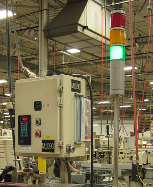
The machine used in this example has no network connectivity but is equipped with 3 stack lights which makes wiring pretty simple. The lights show states producing (green), manual mode (yellow) and error (red).
FIG 2: Manufacturing equipment with 3 stack lights
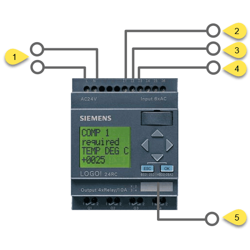
STEPS
Pull 2 wires from the machine’s power supply to the appropriate module power inputs (1).
Connect one side of an additional wire to the machine’s output that feeds the green light and plug in the other side to digital input 1 of the LOGO module (2). Repeat this step for the yellow (3) and red (4) light.
Plug in a network cable to the appropriate jack of the module (5).
Note: LOGO PLCs map PLC program items to specific Modbus addresses. For example, to read the state of Markers M1 to M7 you have to read the bits (coils) of Modbus addresses 8257 to 8263. For reading the state of physical digital or analog inputs no mapping is used.
Address Type
Range
Mapped Modbus Address
Direction
Unit
I
1 - 24
Discrete Input (DI) 1 - 24
R
bit
Q
1 - 20
Coil 8193 - 8212
R/W
bit
M
1 - 64
Coil 8257 - 8320
R/W
bit
V
0.0 - 850.7
Coil 1 - 6808
R/W
bit
AI
1 - 8
Input Register (IR) 1 - 8
R
word
VW
0 - 850
Holding Register (HR) 1 - 425
R/W
word
AQ
1 - 8
Holding Register (HR) 513 - 520
R/W
word
AM
1 - 64
Holding Register (HR) 529 - 592
R/W
word
FIG 4: LOGO PLC address mapping
MODBUSGUI
With the LOGO PLC connected to the machine read from a remote PC:
Read Input Bits 1 to 4, the state of one physical input has to be 1 (ON) all others have to be 0 (OFF)
Read Bits 8257 to 8260, the state of one marker (coil) has to be 1 (ON) all others have to be 0 (OFF)
If your machine outputs a part counter signal and at least one part was produced Read Register 1, the value has to be higher than 0
DEVICE DRIVER
If you’re using the default machine INI file automatically generated by CNCnetPDM the device driver calculates the OEE state of the machine by reading the state of physical digital inputs 1 to 4 of the LOGO PLC.
In case the machine only has 3 stack lights like in this example section [DEVICE STATE] of the INI file has to be adjusted:
Error = 4 has to be changed to Error = 3 and Interrupted = 3 has to be changed to an input that is not connected e.g. 5. It then always stays 0 (OFF).
If you use markers alter Command = readinputbits to Command = readbits and use the mapped Modbus device addresses starting from 8257 (= input 1).
For machines that output a part counter signal section [PART COUNTER] is already configured correctly.
In the device driver INI file you can freely define up to 30 sections to read data from your LOGO PLC with different commands, see the documentation of the device driver.
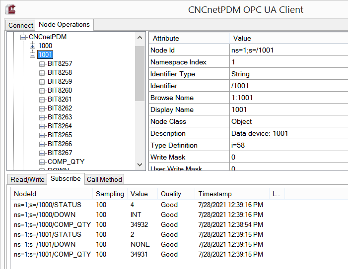
FIG 5: LOGO PLC OPC UA output from 2 devices
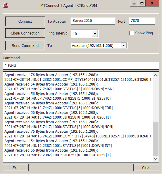
FIG 6: LOGO PLC MTConnect adapter output from 2 devices
TROUBLESHOOTING
If you’re using a firewall at your PC or company network and cannot connect to the LOGO PLC with LOGO Soft Comfort please add an exception for TCP port 8443.
If you know that your LOGO PLC with Modbus support is up and running but you cannot connect with ModbusGui or the CNCnetPDM device driver make sure that neither your PC nor your company network is protected by a firewall that blocks communication with the required TCP port. Add an exception for the port (TCP 502 - 510) to the firewall. Use our tool Device Port Scanner to check if the device is reachable.
If you try to communicate with ModbusGui with a LOGO PLC that is already connected to a different PC the connection succeeds but you only get output ‘Error: No error’. In this case use a different TCP port (503 - 510) or disconnect the other PC from the PLC.